

This ZX Spectrum 128K Toastrack wouldn’t boot after a recap went wrong, and in this third and final part of the series I finally find out why. The Z80’s reset pin had no rise time at all, and the cause turned out to be a tiny trace and via I’d lifted while removing the original capacitors. Here’s how I tracked it down with an oscilloscope, a multimeter and a microscope, and fixed it with a single wire. This video was sponsored by PCBWay.
Earlier in the series, the recap that was supposed to fix this machine ended in disaster, and in part two I built a diagnostics cartridge to dig into it. This episode picks up from there.
How does the Z80 reset circuit work?
To reset the Z80, its reset pin (pin 26) has to be pulled low. A capacitor from the reset pin to ground, plus a pull-up resistor, forms a timing circuit: at power on the capacitor is empty, so the pin starts low and rises gradually to 5V as it charges. That holds the CPU in reset while the rest of the system gets ready. The Z80 only needs to be held low for four clock cycles, which at the Spectrum’s 3.5MHz is around three quarters of a microsecond, so a wide range of values will work, and holding it longer does no harm.
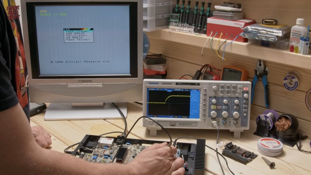
ByteDelight kindly sent me a healthy 128K to compare against. Triggering my oscilloscope on a rising edge with the probe on pin 26, the good machine showed that nice gradual curve. Mine showed no rise time at all.
Why does it boot with a Dandanator plugged in?
Oddly, the broken Spectrum works with a diagnostic cartridge such as the ZX Dandanator Mini inserted. On the scope you can see why: the reset line jumps straight to 5V, then the Dandanator performs its own digital reset, pulling it back to 0V for long enough before releasing it. That second reset overrides the failed one. Leaving a Dandanator plugged in isn’t a fix, but it let me run proper diagnostics, and the rest of the machine passed with flying colours. So the problem was almost certainly in the reset circuit, which the flawed recap had touched.
Checking the capacitor and R31
Modern capacitors can have tighter tolerances than 80s parts, which in rare cases upsets old timing circuits, but I didn’t think that was it. I had already cleaned the reset switch, and the fault didn’t look like a switch problem anyway. In circuit, my ESR meter showed the new electrolytic at exactly 1.00µF with a tiny ESR, about as good as it gets. But that clean in-circuit reading was itself a clue that something was disconnected.
Resistor R31 should be 220K. On the broken board it read just under 219K, perfectly in spec, but on the working board it read about 22.5K in circuit. In a working circuit there’s more than one path between the probes, giving a lower reading; on mine, current could only go straight across the resistor. Something was broken.
Finding the damaged trace
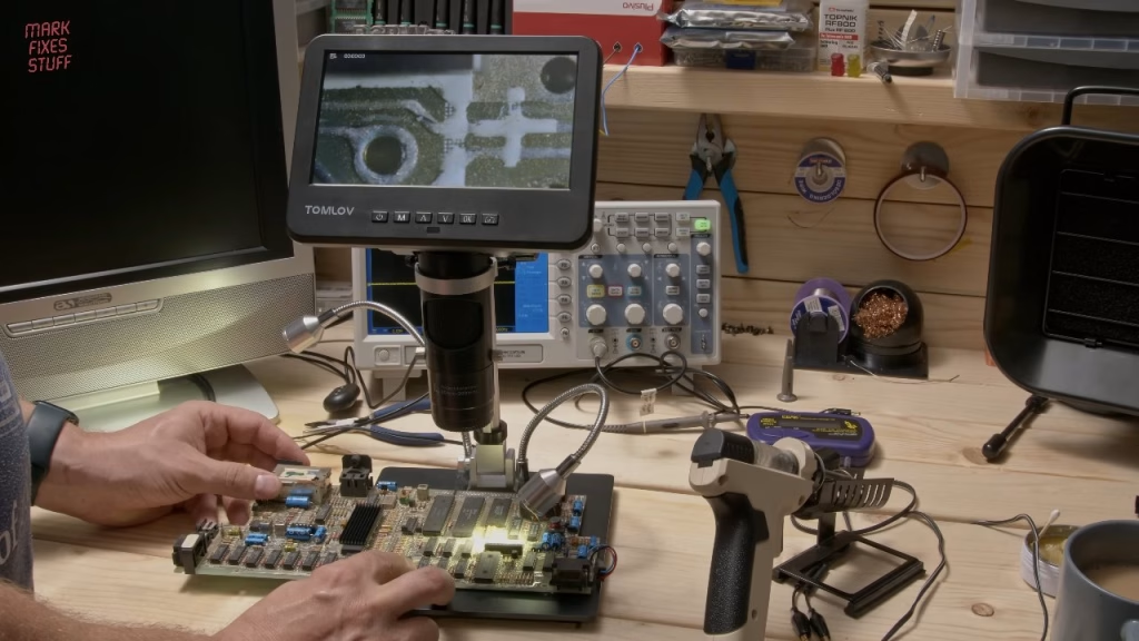
Broken traces are hard to spot on these boards: light-coloured, with unprotected silver tracks, and often hidden under replaced components. With flux paste and my desoldering gun at 330°C, I removed the reset switch wires (the switch tested fine for continuity) and gently wiggled the capacitor out to reuse it. Buzzing out the tracks against the schematic, the capacitor’s negative leg was fine to ground, but there was no continuity from its positive leg to pin 26.
Under the microscope, the cause was hiding exactly where the capacitor body had sat: a trace roughly 0.1mm wide had come away completely, along with the plating ring around its via. It almost certainly lifted with too much heat when the original capacitors were removed. Please don’t judge me too harshly.
The repair
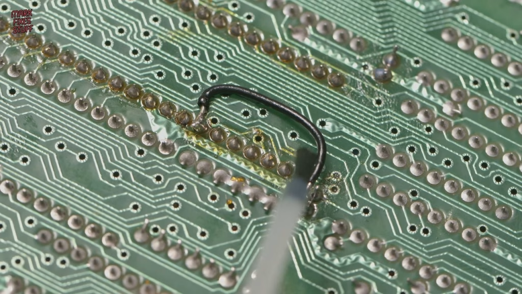
For missing traces I sometimes use magnet wire, scraping the enamel off and soldering it in place, but here that would have been far more work and more heat on an already fragile board. Instead I soldered the capacitor back into the intact part of its via, then ran a jumper wire from its positive side straight to pin 26 on the Z80, bypassing the broken section entirely.
This board uses leaded solder, so I used leaded solder at 330°C, with Blu Tack holding parts in place and soldering iron dwell time kept to an absolute minimum. On the underside, the via runs straight up to pin 26. I used liquid flux to keep heat down, tacked the single-core wire to the reset pin, then bent it across to the capacitor’s positive side. The reset switch and capacitor vias are electrically connected, so I soldered across both for extra strength.
Did it work?
I was nervous connecting up the 7805 regulator. This Spectrum belongs to my friend Jason, it was given to him by someone who has since passed away, and it survived my house fire. At power on, there was the 128K startup screen. Sorry it took years, Jason.
There’s a saying in the retro community: it’s always the caps. Only this time it wasn’t. It was taking the caps out.
To make sure I hadn’t introduced any new faults, I ran the ZX Spectrum Diagnostic ROM by Dylan Smith and Brendan Alford on the Dandanator, which passed and paged the ROM back in. With the keyboard reattached, I loaded Manic Miner. Yes, all that power and I play Manic Miner. The space bar still needs attention, and I’ll clean it up off camera before Jason finally gets it back.
More from the ZX Spectrum 128K Toastrack restoration: Will Recapping Fix This Spectrum 128K Toastrack? Undoing a Botched Recap, Spectrum 128K Toastrack Fix Part 2: Building the ZX Diagnostics Cart.
Related
The Dandanator I used is covered in building the ZX Dandanator Mini 2.1. For more Toastrack repairs, see the Spectrum 128K Toastrack group fix, and if you’re chasing faults like this one, how to test a Spectrum’s 7805 regulator.
Leave a Reply