
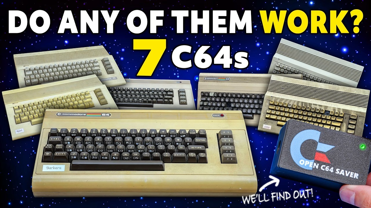
I had a bucket of seven Commodore 64s in completely unknown condition: some given to me, some dumped on me, and two that came out of my house fire. Before I could find out how many still work, I needed a way to power them that wouldn’t kill them, so I built and calibrated an OpenC64Saver to protect them from a failing original power supply. Then all seven went through exactly the same test. This project was sponsored by PCBWay, who supplied the OpenC64Saver PCBs.
Why can an original C64 power supply kill your computer?
The original Commodore PSU supplies 5V DC at 1.7A and 9V AC at 1A. Its known failure mode is the internal 5V regulator going short, which dumps excessive voltage straight into the computer and can destroy chips (RAM especially) within seconds. The 9V AC side isn’t the computer killer here; it’s the 5V DC line you need to watch.
So plugging seven unknown machines into a PSU I didn’t trust wasn’t an option, even though I didn’t expect many of them to work.
It seems unlikely because people don’t give me working things.
Building the OpenC64Saver
The OpenC64Saver by SukkoPera is an open-hardware implementation of Ray Carlsen’s Computer Saver (original documentation here). It monitors the C64’s 5V supply and disconnects it if the voltage rises past a calibrated threshold. You can order the boards from the PCBWay project page.
I started with the resistors, lowest components first. I only had a 1/8W part for the 820R position, but I did the calculations and that’s more than enough for this circuit. R3 is 220K, R4 is 2.2K, and R5 and R6 are both 1K, all quarter watt.
- 1N4732A zener diode as the voltage reference, plus a 1N4148 signal diode.
- Two 2N2222 NPN transistors: Q1 watches the zener and switches on past 4.7V, then drives Q2, which energises the relay.
- A 224 (0.22µF) ceramic disc capacitor on the sensing stage (the schematic says 0.2µF), filtering noise so a blip doesn’t falsely trip the relay.
- A three-pin header for a bicolour red/green LED (anode, cathode, anode, with a shared ground in the middle): green for normal, red when the relay trips.
- A multi-turn trimmer in the divider feeding the zener reference, so the trip voltage can be set precisely.
- A budget SRD-05VDC-SL-C style relay (5V coil, 10A).
- A three-way screw terminal: in, ground, out.
Calibrating the 5V cut-off voltage
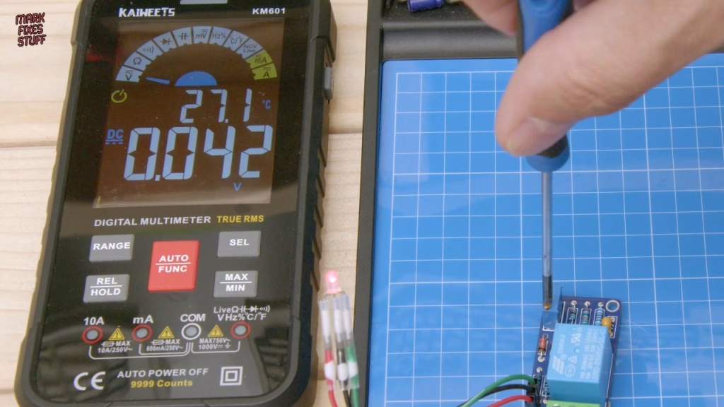
To set the trip point I used a RUZIZAO dual-channel adjustable bench supply. With the supply set to exactly 5V, there was nothing at the output and 5V on the “fail” LED anode, so the Saver had tripped. With the LED wired up, slowing the camera to 20% showed it flash green before the relay snapped off. The threshold was simply set too low.
Adjustment is just a matter of turning the trimmer until the output comes on, then fine-tuning so it cuts off at around 5.4V, which is an acceptable level. With that set, raising the bench supply to 5.5V cut the power, and dropping back to 5.4V and switching on again let it through. (I don’t own a pot tweaker, so I used a metal screwdriver. Sorry.)
Enclosure, wiring and final assembly
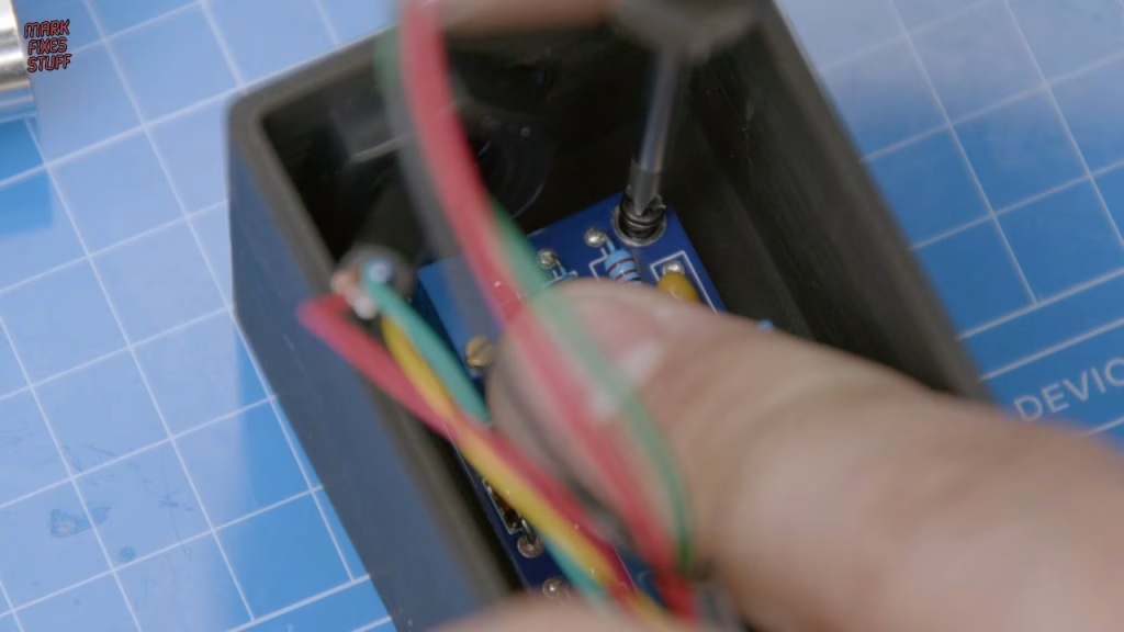
The case linked on the GitHub page goes nowhere, so I took the plunge and designed my own in Fusion then printed it on the Anycubic Kobra X. It has shallow standoffs for the PCB, and to my genuine surprise the board lined up perfectly first time with a couple of small M2 self-tapping screws.
Rather than solder new connectors, I cut an extension cable in half and mapped each pin to a wire colour using continuity mode on my meter. Green is ground and yellow is +5V DC; the 9V AC is on red and black (pins 7 and 6), and a grey wire goes to the shell. The yellow 5V in and out go through the Saver, the two grounds are twisted, tinned and share the ground terminal, and the red and black AC lines are simply joined straight through with solder sleeve butt connectors. Input side gets the female connector, output side the male.
Cable glands keep it tidy, with a cable tie inside each for extra strain relief. The LED is hot glued under the lid, and the lid is a deliberately tight friction fit, so no screws or inserts. With the original Commodore PSU connected through it, the voltages looked good; the AC side was slightly high, which it usually is.
The C64 test matrix
Every machine faced the same checks: power and power LED, boot to BASIC, keyboard, stable picture, SID sound, an Ms. Pac-Man cartridge (one of the PCBs Mike “Lemmings” Dailly gave me), and loading Konami’s Ping Pong from a known-working Datasette.
Mabel, Doris and Ethel
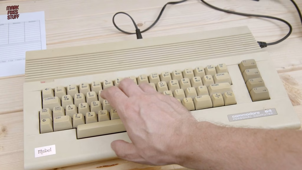
Mabel booted to BASIC with a responsive keyboard and a good stable picture, ran Ms. Pac-Man with sound and loaded Ping Pong. Her only problem is dirt. Doris passed everything too, and is filthy. Ethel was much cleaner and ran Ms. Pac-Man with sound and a working keyboard, but the tape deck didn’t work: one to fix in a future video.
Gladys and Phyllis: the fire-damaged C64s
Gladys was in my house fire and wasn’t wrapped up at the time. She’d also been wet, has rusty ports and a missing key. The power LED came on and the TV knew there should be a signal, but there was no video, with or without the cartridge. A project for another day. Phyllis, an older-style C64 (the “chunky fudge”, as I call it), was in the loft during the fire but was bagged up, and has a broken key post (I do have matching replacement keys). The keyboard seemed dead until I noticed Shift Lock was down. After that she passed everything, Ping Pong included. Phyllis is definitely getting restored.
Maureen and Barbara
Maureen booted, but her keyboard didn’t respond. Her case wasn’t screwed together, so I had a look inside: the keyboard wasn’t even plugged in, and the SID chip was missing altogether. With the keyboard connected, Ms. Pac-Man played fine (silently, of course), but there was no life from the Datasette. Barbara booted, ran Ms. Pac-Man with sound and loaded Ping Pong, although her keyboard isn’t terribly responsive and may need cleaning.
Did it work? How many of the seven C64s still work?
The OpenC64Saver did its job: calibrated, boxed up and showing a green LED with the original PSU behind it. On the C64s, six of the seven booted. Mabel, Doris, Phyllis and Barbara passed every test (with dirt and a sluggish keyboard to sort out), Ethel and Maureen have Datasette problems and Maureen needs a SID, and Gladys gives no video. They all need properly testing and fixing, and I haven’t decided whether to restore them or sell some on. Let me know in the YouTube comments what you think I should do.
Related
More Commodore 64 on the site: the £40 local C64 pickup, my Epyx FastLoad cartridge build, the Kung Fu Flash C64 cartridge review and the Tapuino virtual Datasette build.
Leave a Reply